A primer on TCP/IP
TCP/IP is a little complex, but my no means incomprehensible
Errors or typos? Topics missing? Hard to read? Let us know!
Understanding networking fundamentals is essential for designing, operating, and troubleshooting MAAS networks. TCP/IP networking can seem complex at first, but by breaking it down into layers and core concepts, we can gain a solid understanding of how it works. In this hands-on tutorial, we'll cover:
Centuries ago, John Milton wrote, "I cannot praise a fugitive and cloistered virtue," referring, at least in part, to those who keep their intelligence to themselves. Without some form of communication -- without manifesting that intelligence in word or deed -- there is generally no evidence of intelligence or intelligent life. Our knowledge must create ripples in space and time if it is to be shared, and it must be shared to benefit others.
For this reason, we create networks, which might be defined as "channels of sharing". All virtue and all goodness is valued only in sharing, whether by having mercy on another person or communicating the answer to life, the universe, and everything. Only by sharing do we come to the notice of others, and only with the help of others do we share the load of living.
Channels of sharing are complicated
Sharing involves risk. Will the other person understand? Will they accept what I've shared, or turn against me? Will they appreciate what I have shared, or judge me harshly? All communication involves the risks of misunderstanding, judgement, and ridicule. We must choose carefully when sharing information, tools, knowledge -- even compassion, love, loyalty, and devotion. In a way, that's one of the "equations" of living in a society, although public social media platforms have made that more, er, interesting.
Often we segregate our sharing based on some measurable characteristic. For example, we share with people of our own race, gender, colour, or national origin, but not with the "others". And we share in different ways with different social groups. In fact, you might say that the average person has as many personalities as there are groups of people whose opinions they care about: we are one person at home, another at the office, still another on the Internet, and yet another when we're golfing, as examples. Each of these channels can have different rules, mores, idioms, dialects, and vocabulary.
As we grow up, we learn to be one self, sharing with everyone in very much the same way, restricting only what we share, not how we share it. You begin to deeply understand the basics of human communication. If you're serious about it, you begin to try to normalise your messaging to include less moody prejudice and more honest opinion, modulated only by personal privacy.
Thus it has been with computer networks. For a very long time, there were at least as many network protocols -- selves -- as there were brands and styles of computers. Different methods were needed to share information from one system to another, sometimes even involving specially-crafted physical interface cables to handle the translation.
Eventually, though, computer networks began to gravitate toward a standard approach, "one self to rule them all", as it were. This singular personality is known as TCP/IP.
The history of the internet traces back to the mid-20th century, when computer networking began to take shape. Its origins are closely intertwined with the Plain Old Telephone System (POTS) -- the traditional landline telephone network -- which served as the communications infrastructure before the internet era. Initially relying on circuit-switched networks, POTS faced limitations in data transmission, leading to the birth of packet-switched networks that formed the foundation of the internet.
In the 1960s, the U.S. Department of Defense's Advanced Research Projects Agency (ARPA) pioneered a decentralized communication network, resulting in the creation of ARPANET in 1969. ARPANET utilized packet-switching technology to transmit data packets across interconnected computers. As ARPANET expanded, the need for standardized protocols emerged, leading to the development of the Transmission Control Protocol/Internet Protocol (TCP/IP) in the 1970s. TCP/IP established a common language for diverse computer systems to communicate and laid the groundwork for the modern internet.
Later on, the internet evolved and became more accessible. The emergence of commercial ISPs in the 1990s brought internet access to the general public, while the World Wide Web introduced a user-friendly interface for browsing and accessing information. Today, the internet connects billions of devices globally, facilitating communication, information sharing, e-commerce, and more. The transformation of POTS from circuit-switched to packet-switched networks played a pivotal role in paving the way for the creation of the internet, revolutionizing our modern digital landscape.
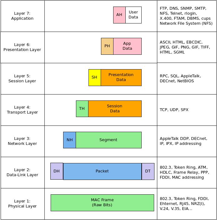
The OSI (Open Systems Interconnection) model provides a conceptual framework for network communication by dividing it into 7 layers:
- Physical - Transmits raw bit streams over a physical medium. Concerned with voltages, frequencies, cable types, connector pins, etc.
- Data Link - Provides node-to-node data transfer across a network medium. Handles MAC addressing, framing, error checking, and flow control.
- Network - Handles logical addressing and routing of data packets over multiple networks. IP and routing protocols like ARP operate here.
- Transport - Manages end-to-end transmission and integrity of data. TCP and UDP operate at this layer.
- Session - Establishes, maintains, and terminates sessions between local and remote applications. Handles session multiplexing.
- Presentation - Formats and encrypts data for the application layer. Deals with syntax and semantics.
- Application - Provides network services directly to end user applications. HTTP, FTP, SMTP etc. operate at this layer.
This standardized model promotes modular design and interoperability between diverse systems. Developed in the late 1970s, it consists of seven layers, namely: Physical, Data Link, Network, Transport, Session, Presentation, and Application. The bottom three layers (Physical, Data Link, and Network) handle data transmission and routing. The Physical layer manages the physical transmission of bits over a medium. The Data Link layer ensures reliable data frame transmission between directly connected devices. The Network layer handles addressing, routing, and logical organization across networks.
The Transport layer focuses on end-to-end data delivery, dividing data into segments and ensuring reliable transport between source and destination. It manages error recovery and flow control. The top three layers (Session, Presentation, and Application) are responsible for user interactions and application-specific functions. The Session layer establishes, maintains, and terminates communication sessions. The Presentation layer handles data formatting, encryption, and compression. The Application layer provides access to network services such as email, web browsing, and file transfer.
While real-world protocols may not strictly adhere to the OSI model, it help a lot in understanding network communication by breaking it down into discrete layers. The model promotes standardization, modularity, and interoperability in networking protocols, facilitating troubleshooting and development.
Enough talk, let's do something
Here's a ping exercise that demonstrates the network layer functionality in the OSI model:
-
Open the command prompt or terminal (hint: on Ubuntu, press
Ctrl + Alt + T-- this works even if you're running Emacs!): -
Type "ping www.google.com" and press
Enter;pingis used to test connectivity and measure the round-trip time (RTT) between your computer and a remote host. By specifying "www.google.com" as the destination, you are pinging Google's server. -
Observe the output, which will display information about the ICMP packets sent and received. Each line represents a round-trip time (RTT) measurement.
pingsends ICMP Echo Request packets to the destination, and if the remote server is reachable, it responds with ICMP Echo Reply packets. The output will show the RTT in milliseconds (ms) for each packet sent and received, along with statistics about packet loss and round-trip times, something like this:
Pinging www.google.com [172.217.169.132] with 32 bytes of data:
Reply from 172.217.169.132: bytes=32 time=13ms TTL=56
Reply from 172.217.169.132: bytes=32 time=12ms TTL=56
Reply from 172.217.169.132: bytes=32 time=14ms TTL=56
Reply from 172.217.169.132: bytes=32 time=11ms TTL=56

Ping statistics for 172.217.169.132:
    Packets: Sent = 4, Received = 4, Lost = 0 (0% loss),
Approximate round trip times in milliseconds:
    Minimum = 11ms, Maximum = 14ms, Average = 12ms
What you just did
pingoperates at the Network layer (Layer 3) of the OSI model. It uses ICMP (Internet Control Message Protocol) packets to test connectivity and measure the RTT between your computer and the destination host.- When you execute the command, your computer constructs an ICMP Echo Request packet and sends it to the destination (in this case, www.google.com).
- If the destination host is reachable and not blocking ICMP traffic, it will respond with an ICMP Echo Reply packet, indicating that the destination is reachable.
- The output displays information about the packets sent and received, including the RTT, TTL (Time-to-Live), and packet size.
- The statistics section at the end provides a summary of the ping session, including the number of packets sent, received, and lost, as well as the minimum, maximum, and average RTT.
By using the "ping" command, you can verify network connectivity, diagnose network issues, and measure the latency between your computer and a remote host, showcasing the functionality of the Network layer in the OSI model.
Let's access a chess server, in the terminal, using ASCII:
-
Open the command prompt or terminal.
-
Type "telnet freechess.org 5000" and press Enter.
-
Watch as you receive a login prompt for an online, ASCII chess server.
What you just did
The "telnet" command establishes a Telnet session with the specified host (freechess.org in this case) at a specific port (5000, in this case). Telnet is an application layer protocol that allows you to remotely access and control another computer or device. This exercise demonstrates how applications can use the Application layer (Layer 7) of the OSI model to provide specific services.
-
Open the terminal: Press Ctrl + Alt + T to open the terminal.
-
Use the ip command to gather information about network interfaces:
ip link show
What you just did
In networking, Layer 1 refers to the Physical layer of the OSI model. It is the lowest layer and deals with the physical transmission of data. Layer 1 interfaces provide the means to connect devices to a network and transfer data in the form of electrical, optical, or radio signals. This command ip link show displays a list of network interfaces -- links -- on your system along with their state, MAC address, and other details. Each network interface -- each "link" -- operates at the Physical layer (Layer 1) of the OSI model.
Here are some more relevant details on the links you might find at this level:
-
Network Interface Card (NIC): A Network Interface Card, commonly known as a NIC or network adapter, is a hardware component that allows a device to connect to a network. It can be an Ethernet card, Wi-Fi card, or other types of interface. The NIC is responsible for converting data from the device into a format suitable for transmission over the network medium, such as electrical signals for wired connections or radio waves for wireless connections. Examples of NICs include Ethernet cards for wired connections or Wi-Fi cards for wireless connections.
-
Ethernet Cable: Ethernet cables are used for wired network connections and are commonly used in home and office environments. They consist of copper wires inside an insulated casing and come in different categories such as Cat 5, Cat 6, or Cat 7, offering varying levels of performance. Ethernet cables connect devices, such as computers or routers, to Ethernet ports on NICs, switches, or routers, enabling the transmission of data at high speeds.
-
Fibre Optic Cable: Fibre optic cables use thin strands of glass or plastic to transmit data as pulses of light. They offer high-speed and long-distance data transmission capabilities, making them ideal for high-bandwidth applications or for connecting geographically distant locations. Fibre optic cables are used in various networking environments, including telecommunications networks, data centres, and high-speed internet connections.
-
Wireless Interfaces: Wireless interfaces, such as Wi-Fi or Bluetooth, enable wireless communication between devices. Wi-Fi interfaces use radio waves to transmit data over the air, allowing devices to connect to a wireless network and access the internet or communicate with other devices. Bluetooth interfaces are used for short-range wireless connections between devices, such as connecting a smartphone to a wireless headset or a laptop to a wireless mouse.
-
Network Connectors: Network connectors are physical connectors that join network cables to networking devices or interfaces. Common network connectors include RJ-45 connectors for Ethernet cables, which are commonly used for wired connections, and various connectors such as LC or SC connectors for fibre optic cables. These connectors ensure a secure and reliable connection between the cable and the networking device.
Layer 1 interfaces, such as NICs, cables, and connectors, play a crucial role in establishing the physical connectivity required for network communication. They handle the transmission of signals, whether electrical, optical, or radio waves, to ensure that data can be sent and received across the network. Understanding Layer 1 interfaces is fundamental in comprehending how devices connect and interact within a network infrastructure.
Let's explore the Data Link layer -- Layer 2 -- which is the next layer up.
MAC addresses
Run the following command:
ifconfig
What you just did
Running the ifconfig command on Linux/macOS or ipconfig on Windows will display the network interface configuration, including the MAC (Media Access Control) address of each interface. You may see the MAC address labelled as ether. The MAC address, also known as the hardware address, is a unique identifier assigned to the network interface card (NIC) at the Data Link layer (Layer 2) of the OSI model.
By "unique", we mean that no other Internet-facing device has the same address, so network devices can find that MAC address in exactly one place in the world. For example, when someone puts your unique street address, city, state, and zip code on a letter, it means that (theoretically) it should only be delivered to one mailbox in the world. By examining the MAC addresses, you can identify the devices or interfaces on the local network, but by their global addresses.
You might notice that the lo (loopback) address doesn't have a MAC address. This is because the loopback is an internal connection that never ventures onto the internet. Think of this like telling someone that "the mail is on the kitchen table" -- it works fine if you're in your own house, but it would only cause confusion if you used "kitchen table" in the outside world.
arp
Type the following command (on Ubuntu):
arp -n
You'll probably get an output something like this:
$ arp -n
Address                  HWtype  HWaddress           Flags Mask            Iface
10.156.28.2              ether   00:16:3e:f6:8b:90   C                     lxdbr0
192.168.1.1              ether   d0:76:8f:e6:94:1a   C                     enx606d3c64581d
192.168.1.101                    (incomplete)                              enx606d3c64581d
192.168.1.247            ether   0c:8b:7d:f1:51:d3   C                     enx606d3c64581d
192.168.1.245            ether   ca:29:14:2b:92:39   C                     enx606d3c64581d
192.168.122.72                   (incomplete)                              virbr0
192.168.1.184            ether   8c:19:b5:b6:d3:c1   C                     enx606d3c64581d
What you just did
The arp (Address Resolution Protocol) command displays and manages the ARP cache, which is used to map IP addresses to MAC addresses. Running arp -a on Windows or arp -n on Linux/macOS will show the current entries in the ARP cache, including IP addresses and associated MAC addresses. The ARP protocol operates at the Data Link layer (Layer 2) and is responsible for resolving IP addresses to MAC addresses within the local network.
Well, we say "operates at Layer 2", but in fact, as you can see from the listing above, it's the go-between for Layer 2 (MAC addresses) and Layer 3 (TCP/IP addresses). More on this later, maybe.
Screwdriver and pliers together
Let's try using the output of ifconfig and feeding it to another tool (ethtool) to get details. Enter this command:
ifconfig | grep -m 1 "^[a-z0-9]*:" | sed -e's/\(^[a-z0-9]*\):.*$/\1/' | xargs -I {} sh -c "ethtool {}"
The output might look something like this, depending upon which of your links is found first by ifconfig:
Settings for enx606d3c64581d:
    Supported ports: [ TP    MII ]
    Supported link modes:   10baseT/Half 10baseT/Full
                            100baseT/Half 100baseT/Full
                            1000baseT/Half 1000baseT/Full
    Supported pause frame use: No
    Supports auto-negotiation: Yes
    Supported FEC modes: Not reported
    Advertised link modes:  10baseT/Half 10baseT/Full
                            100baseT/Half 100baseT/Full
                            1000baseT/Full
    Advertised pause frame use: No
    Advertised auto-negotiation: Yes
    Advertised FEC modes: Not reported
    Link partner advertised link modes:  10baseT/Half 10baseT/Full
                                         100baseT/Half 100baseT/Full
                                         1000baseT/Full
    Link partner advertised pause frame use: Symmetric Receive-only
    Link partner advertised auto-negotiation: Yes
    Link partner advertised FEC modes: Not reported
    Speed: 1000Mb/s
    Duplex: Full
    Auto-negotiation: on
    Port: MII
    PHYAD: 32
    Transceiver: internal
netlink error: Operation not permitted
        Current message level: 0x00007fff (32767)
                               drv probe link timer ifdown ifup rx_err tx_err tx_queued intr tx_done rx_status pktdata hw wol
    Link detected: yes
What you just did
Apart from a little Rube Goldberg CLI magic, this command runs ethtool on a specific link to gather its details. The ethtool command provides information and configuration options for Ethernet interfaces. Running ethtool <interface_name> will -- as you see -- display details such as link status, speed, duplex mode, and supported features of the interface. This command allows you to retrieve information about the Ethernet interface's capabilities and link status at the Data Link layer (Layer 2).
Layer 2 x-ray machine
Try the following command:
ifconfig | grep -m 1 "^[a-z0-9]*:" | sed -e's/\(^[a-z0-9]*\):.*$/\1/' | xargs -I {} sh -c "sudo tcpdump -i {}"
You'll get a never-ending stream of network information (you can stop it by typing Ctrl-c; here's a typical digest of the first few lines:
tcpdump: verbose output suppressed, use -v[v]... for full protocol decode
listening on enx606d3c64581d, link-type EN10MB (Ethernet), snapshot length 262144 bytes
17:54:37.754586 IP ys-in-f102.1e100.net.https > neuromancer.home.32874: UDP, length 261
17:54:37.755120 IP neuromancer.home.32874 > ys-in-f102.1e100.net.https: UDP, length 35
17:54:37.755358 IP ys-in-f102.1e100.net.https > neuromancer.home.32874: UDP, length 1250
17:54:37.755358 IP ys-in-f102.1e100.net.https > neuromancer.home.32874: UDP, length 181
17:54:37.770914 IP neuromancer.home.52240 > router.home.domain: 20554+ [1au] PTR? 100.1.168.192.in-addr.arpa. (55)
17:54:37.772523 IP router.home.domain > neuromancer.home.52240: 20554* 1/0/1 PTR neuromancer.home. (85)
17:54:37.773830 IP neuromancer.home.59034 > router.home.domain: 38747+ [1au] PTR? 102.124.253.172.in-addr.arpa. (57)
17:54:37.790499 IP neuromancer.home.32874 > ys-in-f102.1e100.net.https: UDP, length 32
17:54:37.792160 IP router.home.domain > neuromancer.home.59034: 38747 1/0/1 PTR ys-in-f102.1e100.net. (91)
17:54:37.799052 IP ys-in-f102.1e100.net.https > neuromancer.home.32874: UDP, length 24
17:54:37.805083 IP ys-in-f102.1e100.net.https > neuromancer.home.32874: UDP, length 1218
17:54:37.805454 IP neuromancer.home.32874 > ys-in-f102.1e100.net.https: UDP, length 33
17:54:37.866323 IP neuromancer.home.46036 > router.home.domain: 55474+ [1au] PTR? 1.1.168.192.in-addr.arpa. (53)
17:54:37.868183 IP router.home.domain > neuromancer.home.46036: 55474* 1/0/1 PTR router.home. (78)
17:54:38.004210 d0:76:8f:e6:94:1a (oui Unknown) > 01:80:c2:00:00:13 (oui Unknown), ethertype IEEE1905.1 (0x893a), length 64:
    0x0000:  0000 0000 6128 0080 0100 06d0 768f e694  ....a(......v...
    0x0010:  1a02 0006 d076 8fe6 941c 0000 0000 0000  .....v..........
    0x0020:  0000 0000 0000 0000 0000 0000 0000 0000  ................
    0x0030:  0000                                     ..
17:54:38.531517 IP6 neuromancer.dhcpv6-client > ff02::1:2.dhcpv6-server: dhcp6 solicit
17:54:38.533668 IP6 fe80::d276:8fff:fee6:941a.dhcpv6-server > neuromancer.dhcpv6-client: dhcp6 reply
17:54:38.594705 IP neuromancer.home.40063 > router.home.domain: 20998+ [1au] PTR? 2.0.0.0.1.0.0.0.0.0.0.0.0.0.0.0.0.0.0.0.0.0.0.0.0.0.0.0.2.0.f.f.ip6.arpa. (101)
17:54:38.614325 IP router.home.domain > neuromancer.home.40063: 20998 NXDomain 0/1/1 (165)
17:54:38.614802 IP neuromancer.home.40063 > router.home.domain: 20998+ PTR? 2.0.0.0.1.0.0.0.0.0.0.0.0.0.0.0.0.0.0.0.0.0.0.0.0.0.0.0.2.0.f.f.ip6.arpa. (90)
17:54:38.616383 IP router.home.domain > neuromancer.home.40063: 20998 NXDomain 0/0/0 (90)
17:54:38.895465 IP neuromancer.home.34598 > 192.168.1.247.8009: Flags [P.], seq 1620890202:1620890312, ack 1698989308, win 524, options [nop,nop,TS val 1031552033 ecr 2257976407], length 110
17:54:38.899322 IP 192.168.1.247.8009 > neuromancer.home.34598: Flags [P.], seq 1:111, ack 110, win 677, options [nop,nop,TS val 2257981415 ecr 1031552033], length 110
17:54:38.899435 IP neuromancer.home.34598 > 192.168.1.247.8009: Flags [.], ack 111, win 524, options [nop,nop,TS val 1031552037 ecr 2257981415], length 0
17:54:38.906072 IP neuromancer.home.33717 > router.home.domain: 50660+ [1au] PTR? 247.1.168.192.in-addr.arpa. (55)
17:54:38.907992 IP router.home.domain > neuromancer.home.33717: 50660 NXDomain* 0/0/1 (55)
17:54:38.908297 IP neuromancer.home.33717 > router.home.domain: 50660+ PTR? 247.1.168.192.in-addr.arpa. (44)
17:54:38.909967 IP router.home.domain > neuromancer.home.33717: 50660 NXDomain* 0/0/0 (44)
17:54:39.216802 STP 802.1d, Config, Flags [none], bridge-id 0000.d0:76:8f:e6:94:1a.8003, length 35
17:54:39.810480 IP neuromancer.home.42579 > yi-in-f100.1e100.net.https: UDP, length 176
17:54:39.828278 IP yi-in-f100.1e100.net.https > neuromancer.home.42579: UDP, length 28
17:54:39.839019 IP neuromancer.home.42579 > yi-in-f100.1e100.net.https: UDP, length 33
17:54:39.846436 IP neuromancer.home.44791 > router.home.domain: 8318+ [1au] PTR? 100.138.125.74.in-addr.arpa. (56)
17:54:39.865344 IP router.home.domain > neuromancer.home.44791: 8318 1/0/1 PTR yi-in-f100.1e100.net. (90)
17:54:39.871586 IP yi-in-f100.1e100.net.https > neuromancer.home.42579: UDP, length 619
17:54:39.871586 IP yi-in-f100.1e100.net.https > neuromancer.home.42579: UDP, length 35
17:54:39.871586 IP yi-in-f100.1e100.net.https > neuromancer.home.42579: UDP, length 252
17:54:39.872203 IP neuromancer.home.42579 > yi-in-f100.1e100.net.https: UDP, length 36
17:54:39.876566 IP neuromancer.home.42579 > yi-in-f100.1e100.net.https: UDP, length 33
What you just did
The tcpdump command is a packet analyser available on various Unix-like systems. By using specific filters, such as capturing packets on a specific interface (-i <interface_name>) or based on specific protocols, you can examine Layer 2 frames and their contents in real-time. tcpdump allows you to capture and analyse network traffic, including Ethernet frames, providing insights into the communication at the Data Link layer (Layer 2).
These command line commands provide visibility into Layer 2 aspects of networking, such as MAC addresses, ARP cache, Ethernet interface configuration, and packet analysis. They can help you understand and troubleshoot issues related to Layer 2 connectivity, addressing, and protocols. We'll come back to some of these tools much later on.
Investigate IP addresses and routing
Type the following command and press Enter:
ip address show
What you just did
This command will show the IP addresses assigned to your network interfaces. IP addresses operate at the Network layer (Layer 3) of the OSI model. You can see the assigned IP addresses, subnet masks, and other related information.
IP addresses are fundamental to network communication and are used at the Network layer (Layer 3) of the OSI model. An IP address is a unique numerical identifier assigned to each device connected to a network. It allows devices to send and receive data across networks, enabling communication between different devices and networks on the internet.
IP addresses consist of a series of numbers separated by periods (IPv4) or a combination of numbers and letters (IPv6). IPv4 addresses are widely used and typically written as four sets of numbers ranging from 0 to 255, such as "192.168.0.1". IPv6 addresses are becoming more prevalent and have a different format, represented as eight groups of four hexadecimal digits, separated by colons.
Now, type the following command and press Enter:
ip route show
What you just did:
This command will display the routing table, which lists the available routes to different networks. It includes information about the destination network, gateway, and interface used for routing. Routing operates at the Network layer (Layer 3) of the OSI model.
Routing is the process of directing data packets from a source device to a destination device across interconnected networks. It occurs at the Network layer (Layer 3) of the OSI model. Routers, which operate at this layer, play a crucial role in the routing process.
When a device sends data to a destination, the data is divided into packets, each containing the source and destination IP addresses. Routers examine the destination IP address of each packet and determine the best path or route to reach the destination network. They make routing decisions based on routing tables, which contain information about available routes and associated metrics.
Routers use protocols such as OSPF (Open Shortest Path First) or BGP (Border Gateway Protocol) to exchange routing information and update their routing tables dynamically. This enables routers to adapt to changes in network topology, find the most efficient routes, and ensure that data packets are delivered accurately and efficiently across the network. Routing allows devices on different networks to communicate with each other, enabling data to traverse multiple networks and reach its intended destination.
Type the following command and press Enter:
ss -tunap
You'll see output that looks similar to this:
tcp   LISTEN     0      128                                           [::]:17500                       [::]:*        users:(("dropbox",pid=2746,fd=59))
tcp   LISTEN     0      10     [fe80::b9e0:1f84:f462:319a]%enx606d3c64581d:53                          [::]:*
tcp   LISTEN     0      10     [fe80::b9e0:1f84:f462:319a]%enx606d3c64581d:53                          [::]:*
tcp   LISTEN     0      10     [fe80::b9e0:1f84:f462:319a]%enx606d3c64581d:53                          [::]:*
tcp   LISTEN     0      10     [fe80::b9e0:1f84:f462:319a]%enx606d3c64581d:53                          [::]:*
tcp   LISTEN     0      10     [fe80::b9e0:1f84:f462:319a]%enx606d3c64581d:53                          [::]:*
tcp   LISTEN     0      10     [fe80::b9e0:1f84:f462:319a]%enx606d3c64581d:53                          [::]:*
tcp   LISTEN     0      10     [fe80::b9e0:1f84:f462:319a]%enx606d3c64581d:53                          [::]:*
tcp   LISTEN     0      10     [fe80::b9e0:1f84:f462:319a]%enx606d3c64581d:53                          [::]:*
tcp   ESTAB      0      0                         [fd42:60eb:6f56:329a::1]:5251    [fd42:60eb:6f56:329a::1]:44536
What you just did
This command will show active TCP and UDP connections on your system, along with their respective protocol information. TCP and UDP operate at the Transport layer (Layer 4) of the OSI model. You can see the local and remote IP addresses, port numbers, and connection states.
There's an old joke you can use to remember these options to ss: "You can tune a piano, but you can't tuna fish" (ss -tunap).
Layer 5 of the OSI model, the Session layer, primarily handles session establishment, maintenance, and termination between communicating systems. It is responsible for managing dialogue coordination and synchronization. However, the Session layer is more abstract and typically implemented within the application layer protocols rather than being directly accessed through command-line commands. Layer 6 of the OSI model, the Presentation layer, is responsible for the representation and transformation of data in a manner that is independent of the application layer syntax. It focuses on ensuring that data from the application layer of one system can be properly interpreted by the application layer of another system. Sadly, there are no specific command-line commands that provide direct, basic tutorial insight into Layer 5 and 6 functionalities.
But we can certainly take a good look at Layer 7. Type the following command and press Enter:
sudo lsof -i
Representative output would look something like this, roughly:
COMMAND      PID            USER   FD   TYPE  DEVICE SIZE/OFF NODE NAME
systemd        1            root  106u  IPv6   34911      0t0  TCP *:ssh (LISTEN)
systemd-r    948 systemd-resolve   13u  IPv4   31933      0t0  UDP localhost:domain
avahi-dae   1116           avahi   12u  IPv4   28216      0t0  UDP *:mdns
NetworkMa   1191            root   27u  IPv4   33515      0t0  UDP neuromancer.home:bootpc->router.home:bootps
postgres    1379        postgres    3u  IPv4   35163      0t0  TCP localhost:postgresql (LISTEN)
dnsmasq     1744 libvirt-dnsmasq    3u  IPv4   38180      0t0  UDP *:bootps
tor         1836      debian-tor    6u  IPv4   33600      0t0  TCP localhost:9050 (LISTEN)
slapd       1866        openldap    9u  IPv6   33551      0t0  TCP *:ldap (LISTEN)
proton-br   2680      stormrider   14u  IPv4   41368      0t0  TCP localhost:1143 (LISTEN)
dropbox     2746      stormrider   40u  IPv4 8770210      0t0  TCP neuromancer.home:46568->162.125.21.2:https (ESTABLISHED)
lxd         3550            root   20u  IPv6   41323      0t0  TCP *:8443 (LISTEN)
sshd      221835            root    3u  IPv6   34911      0t0  TCP *:ssh (LISTEN)
cupsd     328391            root    7u  IPv6 6125279      0t0  TCP ip6-localhost:ipp (LISTEN)
cupsd     328391            root    8u  IPv4 6125280      0t0  TCP localhost:ipp (LISTEN)
postgres  372592        postgres    5u  IPv4 7066887      0t0  TCP localhost:5434 (
chrome    405575      stormrider  310u  IPv4 8285829      0t0  UDP 224.0.0.251:mdns
ssh       407687      stormrider    3u  IPv4 7680407      0t0  TCP neuromancer.home:57418->stormrider:ssh (ESTABLISHED)
python3   417174            root    9u  IPv6 7864004      0t0  TCP *:5249 (LISTEN)
rsyslogd  417289            root    5u  IPv4 7869618      0t0  TCP *:5247 (LISTEN)
chronyd   417291            root    3u  IPv4 7866040      0t0  UDP localhost:323
named     417334            root   40u  IPv4 7867212      0t0  TCP localhost:954 (LISTEN)
squid     417573     snap_daemon    8u  IPv6 7868077      0t0  UDP *:48082
nginx     417623            root    5u  IPv6 7873193      0t0  TCP *:5248 (LISTEN)
dhcpd     417667            root    9u  IPv4 7873979      0t0  UDP *:bootps
As you can see, lsof lists open network connections and the associated processes on your system. It can help identify higher layer protocols and services running on specific ports. Protocols such as HTTP, FTP, SSH, or DNS operate at the Application layer (Layer 7) of the OSI model. Understand that is isn't a process list, just a list of processes that are actively using network connections.
Now that you have some tools we can use to prove our points, let's back up and walk through the theory of TCP/IP networks, a little more slowly this time.
A network could be nothing more than a bunch of computers connected with wires. This isn't efficient or affordable. Obviously, many wires are hard to keep straight. Also, impedance would dampen the signals after a relatively short run of wire. An easier way is the Internet infrastructure, which is an access-aggregation-core (AAC)^ network. AAC looks something like this:
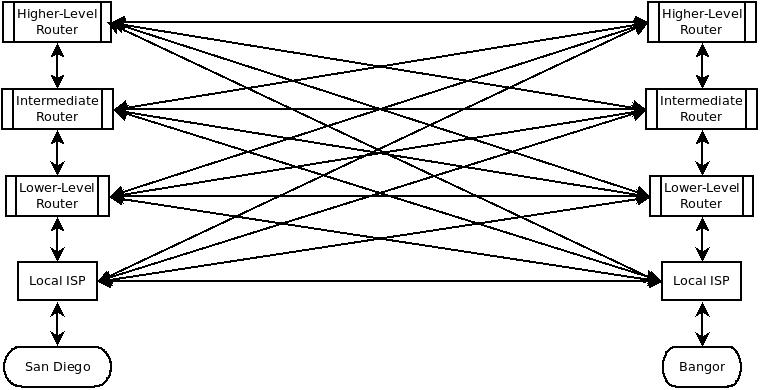
Routers are the multiplexing elements in AAC networks. Ladders of lateral paths aren't theoretical; they exist mostly for performance reasons, like latency, redundancy, cost, and so on. This means an AAC network incorporates redundant loops or "packet-traps". TCP/IP has a dedicated solution for this problem, called "Time To Live"^.
Issues with ladder networks drove the development of cloud network architectures (also known as Clos architectures), which address financial and performance impacts of large networks in a much simpler way. Cloud networking is covered elsewhere, and should be next on your reading list.
Network switching^ is a very large topic unto itself. It's worth catching up if you're weak in this area, since some elements of switching are exposed in MAAS networks. Also important to review are routers^, bridges^, and bonded NICs, aka link aggregation^. All of these come into play every time a MAAS network is modified.
Yesterday's phone network is today's Internet
Most of today's modern networking is a direct translation of the landline telephone system into the digital space. Network switching is really just an outgrowth of crossbar^, which is how local phone calls were "switched" or "routed" to the correct telephone line. In most cases, every number dialled closed one more relay, with all seven relays making a connection to the target phone line.
Small exchanges often "swallowed" dialled digits. For example, if every local phone number had the exchange "881", those numbers wouldn't trigger any relays beyond just sending the call to the "881" frameset^. In some small exchanges, it wasn't even necessary to dial the exchange, just the four digits of the phone number, if the caller had the same exchange. Essentially, these were the early subnets^.
Over time, the increasing density of telephone coverage and self-service long-distance changed all this. More wires had to be installed, and repeaters were needed to get signals across longer distances as local exchanges were replaced by centralised exchanges called "central offices" (CO). A CO would have frames for 8 or 10 exchanges, essentially serving the same function as today's network routers.
Repeaters had to be installed at regular intervals to overcome the impedance associated with longer wires. Those colour-camouflaged, "go-away-grey" metal cans (called pedestals) popped up everywhere, partly for easy re-routing of wires, and partly to house repeaters. We still have those in today's networks, but they're called racks or patch-panels.
In the very early days of long-haul networking, most of the repeaters were owned by the local telephone companies. T1 lines, as they were called, couldn't compete with today's fibre connections, but they did provide a speedy (at the time) 1.5Mbps connection. For example, in the oil and gas industry of the early 1990s, many of the city offices had wall after wall of T1 lines wired directly into the building.
T1 wasn't designed for network traffic, exactly, The idea was to multiplex phone calls on one line via Time-Division Multiplexing. TDM split up the call traffic into little digital packets that were sent on a rotating basis. The first T1 lines, which showed up around 1962, could handle about 24 calls without the average telephone user noticing. Telephone linemen generally could tell by the "clipped" nature of the call, as there is a distinctive flatness to the conversation over a digital TDM circuit. These "little digital packets" formed the model for the packet networking we have today.
The T1 lines used ordinary, double-twisted-pair copper wiring, with repeaters at roughly one-mile intervals (about every fourth pedestal). When WAN and MAN networking became a thing, the phone company just repurposed some of those pairs to carry data traffic. Many other key elements of TCP/IP, like twisted-pair Ethernet cables, packet-based messaging, and multiplexing, are all just holdovers of the original telephone system, repurposed for computer networking.
More about Internet infrastructure
The Internet is theoretically survivable because every computer can connect to every other computer. That's not standard operating procedure. High-level networks (Network Service Providers, NSPs)^ connect to at least three top level nodes called Network Access Points (NAPs), aka Internet Exchange Points^. At these points, packets to jump from one NSP to another. NAPs are public access points, Metropolitan Area Exchanges are private. These are virtually indistinguishable for the purposes of this discussion.
As an aside, many of the MAEs are the residue of the phone company's early T1 lines, which was the initial backbone for the Internet. These MAEs act just like a NAP for the purposes of this discussion.
A simpler picture of the Internet infrastructure looks like this:
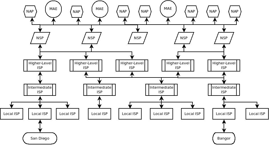
In theory, the Internet infrastructure and a cloud network should be very similar. In practice, they diverge greatly. The real Internet has horizontal connections running everywhere, based on drivers like cost, security, and performance. Those vertical connections introduce an interface cost (heterogeneous hardware), a performance hit (varying network speeds), and bandwidth variance (differing node architectures). Contracts for lateral connections change daily, which changes the routing, which changes the way the Internet behaves for users.
About Internet network traffic
On-the-fly, Internet network paths can become very complicated and somewhat unpredictable. As a result, there's rarely a reason to even count how many hops a message takes, or where it hops, unless you're trying to debug a broken route with, say, traceroute^. From a TCP/IP point of view, it's much easier to ignore the specific network, since each one is custom built, so to speak. The path can theoretically change every time a message is sent, even between the same two computers.
When it comes to designing and troubleshooting networks, knowing the specific route (almost) never helps. What we do want to know about is the network traffic between computers. We have to understand what kind of data travels between computers, besides just the data we send. Internet data flows are governed by the OSI model.
This subsection will help you learn about the OSI model and:
- About the physical layer (L1)
- About the datalink layer (L2)
- About the network layer (L3)
- About the transport layer (L4)
- About the session layer (L5)
- About the presentation layer (L6)
- About the application layer (L7)
Networks are really just continuous wires. We need to understand what travels on those wires, which depends on our perspective -- our level of magnification. At the highest "zoom" level, all we'll see are electrons travelling down the wire; that's a level of abstraction that isn't comprehensible for debugging purposes. About all we can tell is whether or not the circuit's dead.
The Open Systems Interconnection model^ was created to standardise on a few different levels. The OSI model looks something like this:
The OSI model starts just above the raw physics, with the physical layer, also known as Layer 1.
The choice of "1" makes sense, because this is the lowest level we consider. Layers are normally added on top of each other. For example, if you put six coats of varnish on a piece of furniture, you're going to have six layers. The first layer you put on wouldn't sensibly be called "layer 6"; neither network layering work that way.
Here's a quick rundown of what each layer does. Most likely, we won't get into details about all the layers, because the higher you go, the more widely they vary with the user application. Higher layers don't really help us better understand MAAS networking, any more than watching electrons travel through a wire help us debug a missing packet.
The phrase "physical layer" may conjure up notions of physics, but don't worry: we look at signals, not electrons. Here you can learn about the basics of the physical layer, and also:
At the physical layer, we're looking for binary (on/off) signals, set to the cadence of a clock. Every computer brings its own clock to the party, so we definitely need a way to "synchronise our watches". NTP^, the network time protocol, does the trick.
Variable latency is the important thing to know about the physical layer, because it affects the timing of network traffic. In order to understand variable latency, we need to understand network latency. Packets aren't sent without some delay, because of:
- The processing delay - how long it takes the router to process the packet header.
- A queuing delay - how long the packet sits idle in routing queues.
- Transmission delay - how long it takes layer 1 to push the packet's bits onto the link.
- Propagation delay - how long it takes the bits to travel through the wire to the other end.
The size of the queue directly influences how fast data can get onto the link. The processing and transmission delays are real, though relatively constant. The propagation delay doesn't just depend on the speed of light, because there may be lots of other "relay" computers in the link. Propagation depends on network architecture, network congestion, and the number of hops (how many routers between source and destination), among other things. As we'll see later on, within your enterprise, modern cloud architectures usually create significantly less propagation delay.
Variable-latency networks are "variable" because of the density of network traffic and the complexity of the route between hosts. We can't predict congestion or routing, although we can influence local routing by choosing the right network architecture. We can't predict transmission delays, though we can statistically bound them. Almost all digital networks are considered "variable-latency".
The physical layer is not very interesting
Other than verifying that signals are flowing, the physical layer doesn't usually tell us much about what happened to that DHCP request that never made it to the router. Consequently, we really won't talk that much about the physical layer. Just know that it's the thing that's passing bits back and forth between hosts, and very occasionally, we need to scan it to debug network issues.
The datalink layer (the "link" layer, layer 2 or "L2") has one purpose: send and receive IP datagrams. L2 doesn't maintain a connection with the target host; it's intentionally "connectionless", and it doesn't guarantee delivery or integrity of packets. It just ships them between source and destination. This subsection will help you learn:
- About MAC frames
- About Ethernet
- About Media Access Control (MAC)
- About trunking VLANs
- About VLANs, subnets, and fabrics
- How to visualise the link layer
At first, the message-agnostic state of the link layer may seem a little weird. L2 is not without error-checking and recovery code, but it functions efficiently because it isn't concerned with the data or the message containing the data. That fact can be surprising, since L3 packets are called "datagrams".
A datagram is just a basic network transfer unit -- the indivisible unit for a given layer. If we're talking about the data-link layer (aka the "link" layer), it's an IEEE 802.xx frame. At the network layer, it's a data packet. For the transport layer, it would be called a segment. Indivisible units in the physical layer are called chips, which are spread-spectrum pulses in the CDMA, noise-utilising transmission system that operates at that layer.
Since datagram isn't carefully used by everyone (think of User Datagram Protocol), we'll agree to call these indivisible layer units PDUs (protocol data units). This avoids conflation with other uses and reminds you that it's the atomic unit at the current network layer. Just remember that, at the link layer (L2), it's a frame.
A MAC frame, or just "frame", encapsulates the packets from the network layer so that they can be transmitted on the physical layer. A frame can be small or big, anywhere from 5 bytes up to the kilobyte range. The upper size limit is called the maximum transmission unit (MTU) or maximum frame size. This size is set by the particular network technology in use.
This last observation brings up a good point: In order to talk sensibly about frames, we'd need to say what kind of frame. With MAAS, we're always talking about packet-switched networks, so there are potentially four frame types to consider: Ethernet, fibre channel, V.42, and PPP (point-to-point protocol).
Happily, MAAS networks almost exclusively use Ethernet, as defined in the IEEE 802 standards^, so we'll stick to that particular frame type for this discussion. Where other frame types may come into play, we'll discuss those as special cases.
Before explaining an Ethernet Frame, we need to give a little background information about how Ethernet works; otherwise a lot of the frame components either won't make sense, or you'll wonder how it works at all.
Remember earlier, when we talked about voice radio, and the need to say "over"? Well, Ethernet at the link layer is all about controlling the conversation, so that computers don't "talk over each other". Ethernet implements an algorithm called CSMA/CD, which stands for "carrier sense multiple access with collision detection." This algorithm controls which computers can access the shared medium (an Ethernet cable) without any special synchronisation requirements.
"Carrier sense" means that every NIC does what humans do when we're talking: it waits for quiet. In this case, it's waiting for the network to be quiet, that is, when no signal is being sent on the network.
"Collision detection" means that, should two NICs both start to send on a shared network at the same time (because the network was quiet), they each receive a jam signal. This signal tells them to wait a specific, randomly-generated amount of time before attempting again. Every time subsequent messages collide, the NIC waits twice the amount of time it previously waited. When it waits some maximum number of times, the NIC will declare a failure and report that the message didn't go. This ensures that only one frame is traversing the network at any given time.
About Media Access Control (MAC)
Systems like CSMA/CD are a subset of the Media Access Control (MAC) protocol kit. MAC is one-half of the link layer, with Logical Link Control (LLC) being the other half -- though these are sometimes called sub-layers. LLC mostly just defines the frame format for the 802.xx protocols, like WiFi, so we can safely ignore it for the purposes of MAAS networking.
If you've worked with networks at all, you've heard of MAC addresses. Those are basically unique serial numbers assigned to network interface devices (like NICs) at the time of manufacture. Theoretically, they are unique in the world, not counting virtual NICs in virtual machine environments. MAC address collisions^ do happen when using VMs, and there are ways to fix it, assuming that your VMs are confined to a subnet.
The MAC sub-layer is connected to the physical layer by a media-independent interface (MII), independent of the actual link protocol (e.g, cellular broadband, Wi-Fi radio, Bluetooth, Cat5e, T1, ...). You can learn more about the MII^ if you're so inclined, but we won't address it again in the context of MAAS networks.
Essentially, the MAC sub-layer grabs higher-level frames and makes them digestible by the physical layer, by encoding them into an MII format. It adds some synchronisation info and pads the message (if needed). The MAC sub-layer also adds a frame check sequence that makes it easier to identify errors.
In conventional Ethernet networks, all this looks something like the following:
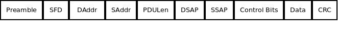
Let's decode those blocks of bits:
-
The Preamble is 7 bytes of clock sync, basically just zeroes and ones like this: ...0101010101.... This gives the receiving station a chance to catch up and sync their clock, so the following data isn't out of sync (and thus misinterpreted). To delve just a little deeper, the Preamble helps the receiving NIC figure out the exact amount of time between encoded bits (it's called clock recovery). NTP is nice, but Ethernet is an asynchronous LAN protocol, meaning it doesn't expect perfectly synchronised clocks between any two NICs. The Preamble is similar to the way an orchestra conductor might "count the players in" so they all get the same rhythm to start. Before clock recovery, there was MPE. Clock recovery is much more reliable than trying to get computers all over the world synced up to the same clock frequency and the same downbeat (starting point). Ethernet actually started out that way with something called Manchester Encoding or Manchester Phase Encoding (MPE). This was important because electrical frequency varies not only across the world, but also from moment to moment when the power is slightly "dirty". MPE involved bouncing a bit between two fractional voltages using a 20MHz oscillator to generate a reference square wave. It works, but it's not very efficient, so MPE was scrapped in favour of using the Preamble, the way that projectionists use alignment marks on reels of movie film.
-
The Start Frame Delimiter (SFD) is the last chance for clock sync. It is exactly 10101011, where the "11" tells the receiving station that the real header content starts next. The receiving NIC has to recover the clock by the time it hits the SFD, or abandon the frame to the bit bucket.
-
The Destination Address (DAddr) is six bytes long, and gives the physical address -- the MAC address -- of the next hop. Be aware that the next hop might be the destination, but it's also possible that the next hop might be a NAP, MAE, NSP, or intermediate ISP. It's basically the next address in the direction of the destination that the sender knows about. Unlike the Source Address, the Destination Address can be in a broadcast format (similar to a subnet like 192.18.0.0, but using MAC addresses).
-
The Source Address (SAddr) is also a six-byte MAC address, this time the MAC address of the sender, which does not change as long as the message is traversing only layer-2 (Ethernet) switches and routers.
-
The PDU Length (PDULen) gives the byte length of the entire frame, assuming that it's 1500 or less. If it's longer than that, it indicates a message type, like IPv4, ARP, or a "q-tagged" frame, which carries a VLAN ID.
-
The DSAP, SSAP, and Control elements are each one byte in length, and help define devices and protocols. For the most part, we won't be worried about these with MAAS networks. Just know that as more and more 802 point-standards come out (e.g., 802.11, WiFi), these elements get longer and more complex.
-
The Data or "Payload" is the actual packet being sent, which in the case of TCP/IP, is just a TCP header attached to a fixed-length chunk of the application's data. It's passed on from the layer above. It cannot be less than 46 bytes, and in conventional Ethernet, it cannot be larger than 1500 bytes. If the actual data is too small, it's padded out to 46 bytes.
-
The CRC or "Frame Checksum" (FCS) is a standard checksum, used to verify that the message hasn't been corrupted along the way.
The Preamble and SFD are often considered to be part of the IEEE "packet", so some people start counting the "frame" at the Destination Address. That distinction shouldn't affect anything we do with MAAS networks, but it's nice to keep in mind, in case you run into someone who groups packets differently than you do.
There is a crucial modification to the basic frame format called a P/Q or VLAN Tag. This allows something called VLAN trunking, which means sending all the VLAN data over the same wire and port, but giving the NICs a field (the P/Q tag) to control access. On paper, it looks something like this:
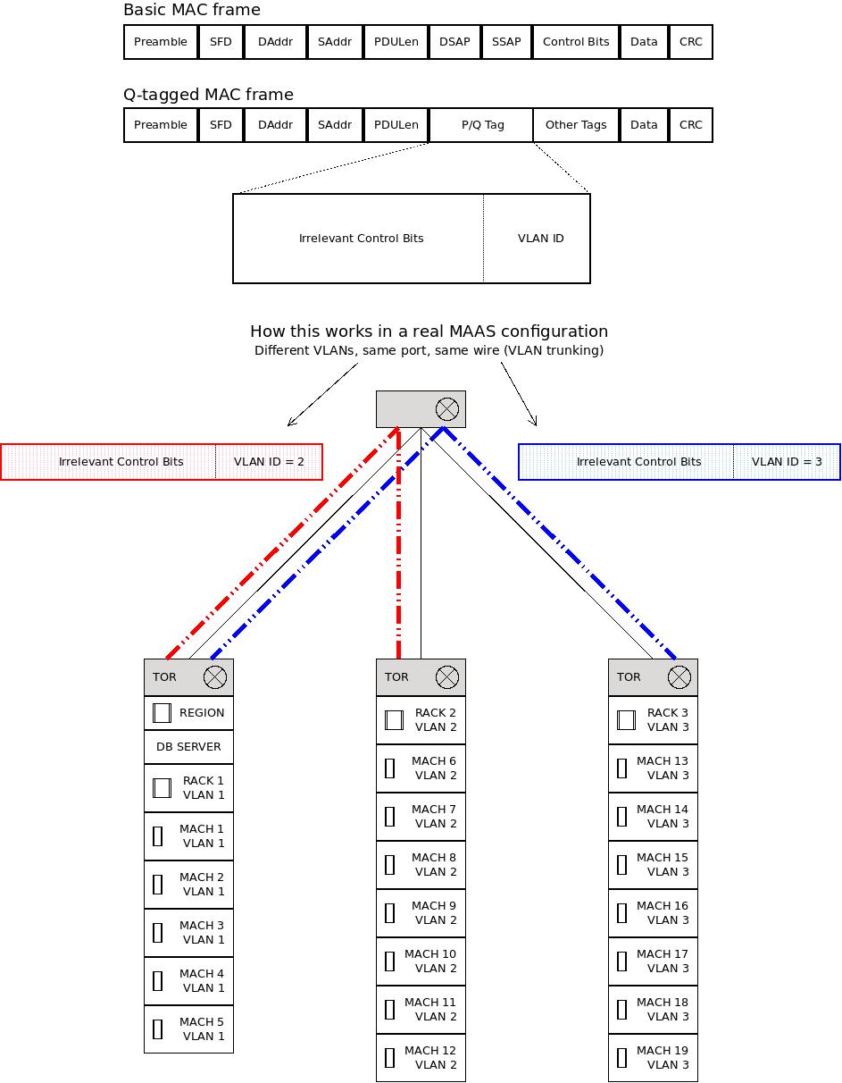
As you can see in the modified P/Q frame, the following fields replace part of the frame:
-
Sixteen bits of tags or a protocol ID.
-
Three bits representing a priority.
-
One bit is used as a Canonical Format Indicator (CFI), which is 0 if the following VLAN ID is in Ethernet format, or 1 if it's in Token Ring format.
-
Twelve bits of VLAN ID.
This matters when we're building complex MAAS networks with lots of VLANS that probably cross over switches. After all, VLANs were initially controlled with ports and switches, although they more commonly use tags now. When more than one VLAN spans multiple switches, frames need to carry VLAN information that can be used by switches to sort or "trunk" the traffic.
The word "trunking" is derived from the telephone network term trunk lines, which are lines connecting switchboards.
In the original telephone company model, each telephone had a subscriber line, which was a wire that went straight from the local Central Office (CO) to that subscriber's telephone. Each CO had one switchboard, though it might have many seats.
Connections between Central Offices were handled by trunk lines, because they ran between phone company facilities. You'd have a thick cable with lots of pairs running from CO to CO, basically enough wires to handle something like 35% of the possible calls. If you ever got the message, "All circuits are busy now; please try your call again later", you've heard what happens when the system is "trunking above capacity" or "TAC'd", as it was called.
At the CO, the wires would "branch" and run all over the place: First to junction points (those five-foot-tall boxes you see from time to time on the road), then to interface points (the square cans beside the road every half mile or so, also called "pedestals") and from there to subscriber homes. When you draw out this network, it looks like a tree, where the bundles of cables between COs look like the trunks of trees.
With VLAN trunking, by the way, we're not just multiplexing packets, we're actually multiplexing LAN channels, so to speak.
In the parlance of networks, especially VLANs, the term "trunking" is used to indicate the sharing of network routes. This sharing is made possible by the Ethernet VLAN tags, which make the VLAN-bound messages less dependent on switches and routers to get the traffic to the right place. Otherwise, you'd have to designate complicated port configurations for switches, which is particularly easy to misconfigure.
Note that the MAC sub-layer is responsible for managing CDMA/CD, that is, detecting a clear line, initiating re-transmission if there's a jam signal, etc. On the way in, the MAC sub-layer verifies the CRC/FCS and removes frame elements before passing the data up to the higher layers. Basically, anything that some other MAC layer did to encapsulate the message for sending, the receiving MAC layer un-does on the way in.
About VLANs, subnets, and fabrics
When working with MAAS networks, you will frequently be concerned with VLANs, subnets, and fabrics, which are all network groupings:
-
Subnets define (group) a range of IP addresses.
-
VLANs group subnets.
-
Fabrics group VLANs.
Let's give each of these terms a MAAS context.
Subnets
A subnet is a range or collection of IP addresses. A subnet just means "sub-network," and that's exactly what it is: a subset of IP addresses that can be treated like a single block for some operations.
Subnets are defined in CIDR (Classless Inter-Domain Routing) notation. If you want to use the addresses from 192.168.13.0 to 192.168.13.255 in a subnet, you can specify that with 192.168.13.0/24. The "24" refers to the number of bits in the subnet address, with the remainder out of 32 bits free to address hosts. Since 8 bits can represent 256 things, that means /24 gives you the last octet, or 255 host IP addresses.
Whatever happened to subnet classes? Subnets used to be defined in terms of subnet classes, like A, B, and C. That got to be a limitation, because those three classes define a fixed number of bits of the IP address that represent the split between subnet addresses and host addresses. In other words, the class defined how many hosts could be in the network, and three classes wasn't really adequate to address all the possible permutations that network architects needed. The change to CIDR notation made subnets more granular, allowing many more subnets from the same network.
VLANs
A VLAN used to be a series of IP addresses that could access a given port on a specific switch, generally the switch that gated some protected resource. With the advent of VLAN trunking (see above), VLANs are marked with the 802.1Q (P/Q) bits in the MAC frame. In theory, any set of addresses can be associated with any VLAN.
MAAS encourages a correspondence of subnets to VLANs. Every IP should be in exactly one subnet, and every subnet should be part of exactly one VLAN. You don't have to do that: you could, for example, have two different subnets that overlap, like 192.168.43.0/24 and 192.168.43.0/26. The ".26" subnet would use fewer bits for the host addresses, so only some of the addresses would overlap. MAAS generally prevents this kind of address overlap.
Likewise, putting one subnet in two different VLANs might be possible, but it isn't practical or easy to debug when conflicts happen. MAAS endeavours to enforce a clean "fan-out" across the network, with no possibility of conflicting IP addresses.
Fabrics
A fabric just collects VLANs together. If you stick to the clean fan-out, that also means that a fabric collects subnets. A fabric provides a higher level grouping.
Consider a MAAS-centric example. Suppose you have one VLAN for HR, and one VLAN for payroll, so that nobody else can see HR's private files, and likewise you've got payroll data limited to just those people who should see it.
Some executives are entitled to see anything and everything about the corporation. An "executive" fabric would group all VLANs together, so that people admitted to that fabric can access the VLANs without having to be explicitly added to each one. That's very handy in really large organisations, saving a lot of time and effort.
Let's start with a message coming on Layer 1 from SanDiego to Bangor. When the message comes in, the link layer does the following things:
-
It synchronises the NIC, so that bits will indeed be recognised as bits and the message can be properly decoded.
-
It handles the source and destination addresses, using ARP as necessary.
-
It interprets the length/type bytes and uses them, which means it must judge the length of a frame, and of the data in a frame, or, alternatively, decide whether a frame is IPv4, ARP, or VLAN ("q-tagged").
-
It processes VLAN tags, which means, at the very least, dealing with the message priority, deciding whether the VLAN frame is Ethernet or Token Ring, and capturing and using the VLAN ID. The layer handles messages by priority, knows how and when to send Ethernet or Token Ring frames, and knows how to route traffic to a specific VLAN.
-
It computes the checksum to make sure the message is valid.
Next, we'll take a look at the network layer, where most of the message transactions take place, and where most of our debugging will be done.
One frequently asked question is this: Is ARP a layer 2 or layer 3 protocol? Actually, it's both, as you'll discover later, but it does all of its work at L2. One way to distinguish L2 from L3 is to find out what happens inside the firmware of the Network Interface Card (NIC), and that's usually where ARP takes place. ARP maps MAC addresses, which is how things are addressed in L2, into other addresses (e.g., IP addresses), which is how L3 finds things.
You might have noticed in the original OSI model that "IP" was part of Layer 3, and protocol stacks like UDP and TCP were part of Layer 4. It's a little bit confusing that we say "TCP/IP" when the "IP" really applies to so many other protocols like UDP and ICMP. There are certainly other protocols and protocol stacks, but for the purposes of MAAS networks, we're talking almost exclusively about TCP/IP.
This subsection will help you learn:
The network layer does not guarantee delivery. Essentially, it makes every effort to deliver IP datagrams (packets) to the destination, but it's error-handling is pretty simple: just toss the packet into the bit-bucket.
It's also a connectionless layer, meaning the packets making up a message aren't part of an ongoing conversation. They can be split up, encoded, and sent separately, by different routes, and arrive completely out of order. And packets can get duplicated or corrupted. Figuring all this out is the job of the protocol stack (e.g., TCP) in layer 4. The network layer, L3, just delivers packets.
Network byte order: A rarely needed (but useful) fact is that the network sends bytes in big endian order. That means bytes are transmitted starting with bit 0 and working down to bit 31, usually eight bits at a time. A lot of the computers on the Internet use little endian encoding, which starts at the other end of the word. In those cases, the byte order has to be reversed somewhere between the computer's memory and Layer 3. For most situations, that fact isn't particularly useful, but there is the occasional fault that involves failure to reverse byte order along the path from RAM to NIC.
Packets are basic Internet Protocol (IP) message units. A message will probably be split into multiple packets by L4 (the transport layer) so it can be efficiently sent.
For example, imagine that you're sending a very long letter to your friend, and all you have are lots of envelopes and first-class stamps. If you've ever done a lot of mailing, you'll know that mailing a one-ounce letter costs you, say, fifty-eight cents. If you add another ounce of paper to it, that second ounce only costs you, say, twenty cents. But all you have are first class (i.e., fifty-eight-cent) stamps.
If you don't want to waste your money, you can either cram more pages in the envelope, until you're at three ounces (the most you can get with two stamps), or send two letters, each with one ounce in it. The way envelopes go through the mailing system, you're better off not over-stuffing an envelope. So what do you do?
You sit down and write the letter to your friend, carefully numbering the pages. Then you divide it into piles of pages that are just under one ounce. Finally, you put each pile into an addressed, stamped envelope and mail each letter separately. When your friend gets the letters, it doesn't matter which one gets there first, because they can reassemble your message, using the page numbers.
About fixed packet lengths and segmented messaging
We could have designed computer networks to take messages of indeterminate lengths, but that presents some unique challenges when trying to manage network traffic. For example, suppose you send seven overstuffed letters to your friend, and so does everyone else on your block? All these huge letters aren't going to fit in one letter-carrier's bag, so they'll have to either send out two delivery people, or wait until tomorrow to send out someone's letters.
Choosing a fixed (relatively short) length makes it statistically possible for everyone's letters (everyone's messages) to be delivered at a fairly constant, reliable rate. That rate will vary with the size of the overall message, not with who threw their message on the Internet first. A larger message takes longer to send.
Messages are split into packets of consistent length before they're passed to L3, so larger messages take longer. It's statistically more efficient to split messages into equally-sized packets than any other arrangement -- the method that gets the highest count of complete messages through the network in a given amount of time. In network terminology, it's the highest-throughput approach to network traffic. Specifically, this technique is called multiplexing.
The IP datagram (packet) is the backbone of most modern networks. The following diagram depicts an IPv4 header, which attaches to the front of data packets up to about 65K long:
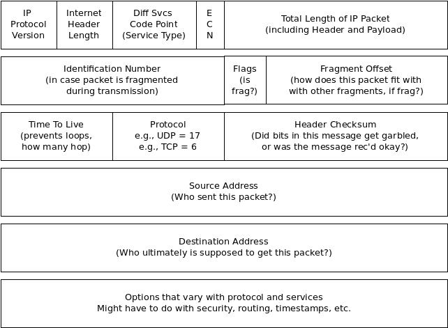
Note that IPv6 headers have only the version field in common with IPv4 headers; otherwise, they are completely different. Here are the header fields and what information they carry:
- IP Protocol Version This is "4" for IPv4 and "6" for IPv6. There are lots of others^, but they generally don't touch a MAAS network.
- Internet Header Length The number of 32-bit words in the header, including the options (but not including the data, since it's just the header). Most of the time, this will have the value "5", but options do exist and are sometimes included.
- Differentiated Services Code Point This is used to specify special classes of service. Normally, IP packets are delivered on a "best-effort" basis, that is, Layer 3 will try everything possible to make sure a packet gets delivered. You can cause L3 to deliver packets with higher priority (implying more certainty) by using a different DSCP.
- ECN = Explicit Congestion Notification These bits are both set by an ECN-capable router when that router is above a certain traffic threshold. They are there to alert a sender to slow down (or expect delays) when the network segment in use is particularly congested.
- Total Length of IP Packet This field indicates the length of the entire packet, including the data. This makes it possible to calculate the byte offset of the data within the datagram.
- Identification This is a serial number, generated by the sending NIC, that helps the participants uniquely identify the datagram. In a sense, it works like the little "take-a-number" tickets you get at the hamburger stand: Eventually, the number will repeat, but the repeat cycle is so long that there's no chance of confusing packets. The sequential nature of this field, when used in concert with the Flags and Fragmentation Offset field, helps the protocol stack correctly reassemble the message.
- Flags This field is basically used to indicate that a packet is a fragment of a longer message.
- Fragmentation Offset Used with the Identification sequence number, this field allows the system to know which packets precede or follow this one when re-assembling the message.
- Time to Live (TTL) This indicates the number of routers that a datagram can pass through before it's discarded. Since routers function by replacing their own destination address with the IP address of the next hop, this essentially limits the number of times a packet's destination IP can be changed. Most RFC documents suggest keeping this number at 64, it's more often set to something like 255 without any real bottlenecks.
- Protocol This field indicates the higher level protocol (the protocol stack) that generated this message. Examples are given for TCP and UDP in the figure.
- Header Checksum This calculates a checksum for the header only. It's only used in IPv4. Doing integrity-checking on the data is the responsibility of Layer 4.
- Source Address This is the IP address of the sender of the packet, for this hop only. As shown in the figure below, routers will change this address so they can get the answer back.
- Destination Address This is the IP address of the destination, for this hop only. As shown below, routers change this address to act as brokers in the IP chain.
We now have enough concepts in play to talk about routing. Routing takes place at the network layer, by changing the source and destination addresses (without losing track of the replaced address). The process looks something like this:
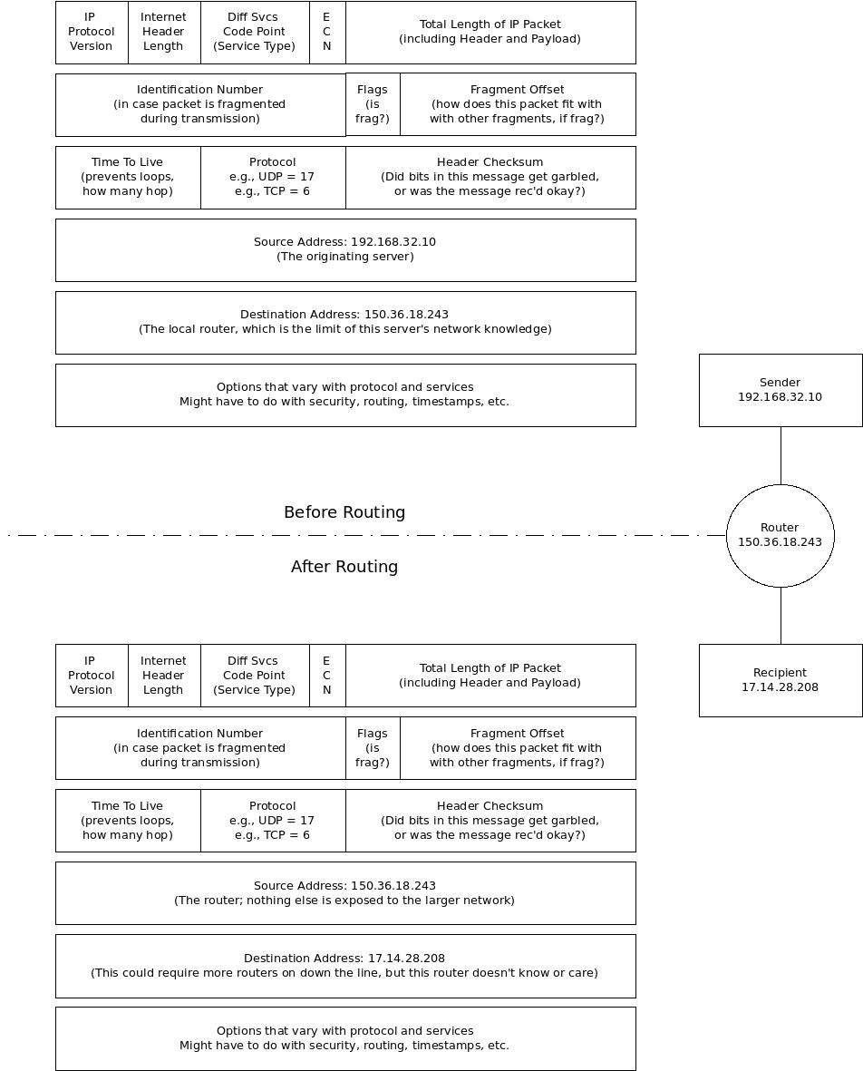
The router typically assigns a unique port number to the outbound message, and records the source IP against that port number. When the message comes back to it on that port number, it can look up the IP address of the NIC that sent the packet and route the answer back.
Layer 4 brings us to protocols implemented only by the end hosts (i.e., not by the routers or other switching gear that connect the network). This layer handles things like redundancy, confirmed delivery, managing packets on an unreliable network, and so forth. This is the last layer that TCP/IP has anything to say about; layers above this are unique to specific applications. Troubleshooting this level would involve knowing about entire protocol sets, like UDP or TCP.
Layer 5, the session layer, is where ongoing interactions between applications happen. The data is couched in terms of things an application might understand (e.g., cookies for a Web browser). This is also the layer where check-pointing (i.e., saving work finished so far) happens. At this layer, we'd discuss things like RPC, SQL, or NetBIOS.
The presentation layer converts data between formats and ensures standard encodings are used to present the information to the application. This layer is all about file formats: ASCII, EBCDIC, JPEG, GIF, and HTML, to name just a few.
The top layer, layer 7, is totally the province of the application(s) involved in processing messages. Two techs talking about this layer would be swapping stories about application protocols, like FTP, DNS, SMTP, or NFS. Almost nothing that happens at this layer -- except for throughput estimates or fouled daemon code -- filters into designing or debugging MAAS networks.
A bond interface is used to aggregate two or more physical interfaces into a single logical interface. Combining multiple network connections in parallel can increase network throughput beyond what a single NIC will allow. It also provides some redundancy in case one of the NICs should fail.
Bonded interfaces use a special frame format called LACPDU, or "Link Aggregation Control Protocol Data Unit. More information about these special frames, and about the theory behind bonded NICs, can be found in the relevant IEEE standard^.
Let's take a short diversion to talk about bridge interfaces. These will be important when we discuss ARP a little further down.
A network bridge may be useful if you intend to use virtual machines or containers with MAAS. Bridges are, to some extent, artefacts of the AAC network. Frequently, people ask about the difference between a switch and a bridge. The core answer lies in the number of ports: switches have as many ports as you can afford; bridges usually have fewer ports, often only two.
Switches traditionally forward packets, without storing them, to a specific host on a specific port, building up a table of host vs. port in the process to reduce broadcast transmissions. Switches traditionally use ASICs (Application Specific Integrated Circuits), otherwise known as "merchant silicon", designed especially for that purpose.
Bridges, on the other hand, provide store and forward packets between two LANs, generally using software. They might still integrate merchant silicon, or even start as an ODM (original design manufacturer) box with no NOS (network operating system), similar to the way some mid-range switches are built. Software added on top, plus the low port count and the store-and-forward approach.
Bridges can use MAC addresses (L2) to direct packets, can essentially emulate L3 routing (recording IP addresses of bridged messages for correct return trips), or some combination of both. Switches usually just route packets between ports.
You can create a network bridge with MAAS; via netplan; or by any other established method to create a network bridge. For example, when you're using LXD, you typically create a virtual bridge, called lxdbr0 by default, that bridges between the MAAS host and the LXD instance. On the host side, the LXD bridge looks like this:
7: lxdbr0: <BROADCAST,MULTICAST,UP,LOWER_UP> mtu 1500 qdisc noqueue state UP group default qlen 1000
    link/ether 00:16:3e:e4:2b:fe brd ff:ff:ff:ff:ff:ff
    inet 10.90.194.1/24 scope global lxdbr0
       valid_lft forever preferred_lft forever
    inet6 fd42:1fc6:f588:d0b8::1/64 scope global
       valid_lft forever preferred_lft forever
    inet6 fe80::216:3eff:fee4:2bfe/64 scope link
       valid_lft forever preferred_lft forever
On the MAAS side, the virtual bridge looks like this:
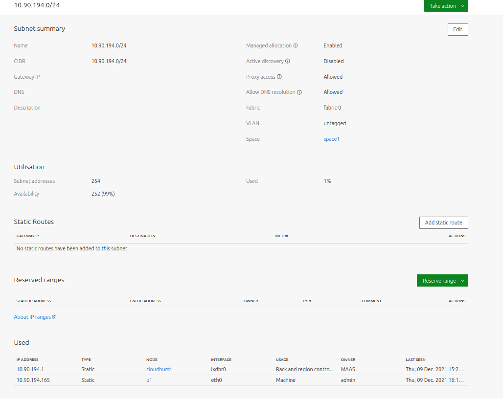
Where the 10.190.94.0/24 network is usually part of a VLAN offering MAAS-provided DHCP:
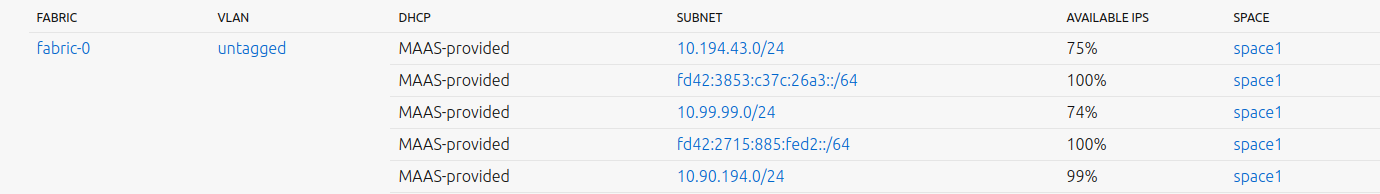
There are other DHCP configurations possible with MAAS (we'll cover this later). The important point here is not to get overly hung up on the terms "switch", "bridge", and "router". Instead, figure out whether you want to forward messages based on port numbers, MAC addresses, or IP addresses -- or some combination -- and then find real or virtual devices that will do this for you.
In theory, every NIC card in the world has a unique identifier, called a /MAC address/. "MAC" stands for "Media Access Control" -- you can find a little history of this^ on Wikipedia, if you're interested.
This subsection will help you learn:
- About TCP/IP vs. MAC addresses
- About fixed versus assigned addressing
- About address resolution
- That messages are sent to MAC addresses
- About the ARP frame
- About the ARP cache
- More about ARP
When you're assigning MAC addresses with virtual machines, of course, you may be re-using one that's actually assigned to a network device out there somewhere. Inside your Layer 2 network, that isn't a problem, because only devices connected to a physical switch -- that's actually connected to the physical Internet -- care about unique MAC addresses. Inside your network, the only conflicts you need to worry about are the ones you create by hand-assigning MAC addresses.
The shorter answer to that implied question is this: MAC addresses must be unique across the domain where they're used.
TCP/IP does not use MAC addresses
If we look at the IP datagram again, we see that it doesn't know about MAC addresses at all:
TCP, UDP, and a number of other protocol stacks are written to use IP addresses. Routers depend on IP addresses, as we've already seen. This creates a bit of a conundrum: How do we map between MAC and IP addresses, and what does the mapping? Is it a layer 2 or layer 3 operation?
The first thing to remember is that the MAC address is "ROM-burned" into the NIC card. IP addresses, on the other hand, are assigned to a NIC by a DHCP server or an administrator. This intentional separation of addressing schemes is what makes the Internet flexible.
Fixed versus assigned addressing
Here's an analogy. Your postal address doesn't /actually/ define where your house is located. There are two layers of other addressing schemes that are actually used by government organisations, like your county tax assessor or the local air ambulance company.
One is your land survey location. Depending on where you live, this is defined by a series of coordinates that go something like this: county, township, section, plat, lot, etc. If you've ever looked at your property tax bill, it will have your postal address on it, but it will not actually use your postal address to define the taxable property. Instead, it uses this unique set of (rather obscure) coordinates to place you exactly on land survey maps.
But that's not good enough for the air ambulance, for two reasons. First, the survey maps are huge, complex, and hard to interpret, and they change somewhat as property is bought or sold. Second, helicopter navigation is intentionally independent of political boundaries. Instead, the air ambulance will use your latitude and longitude, which allows them to uniquely locate you on the earth. Granted, the ambulance company has a tool somewhere that automatically does the maths of translating your postal address to lat/long coordinates, but the principle holds.
In terms of your local network, each of these "address levels" applies. Your postal address corresponds to the IP address of a machine. That IP address may or may not be unique, depending on the domain. For example, you can use Google Maps to try and locate something like "20 Main Street", and you'll get a really long list of responses that vary by city.
Likewise, there are probably hundreds of thousands of local networks using addresses in the "192.168...." subnet, since it's so common for local IP addressing. As mentioned above, routers at the network layer take care of protecting these unique local addresses when going out on the Internet. On the other hand, your NIC's MAC address is like the GPS lat/long coordinates; it's unique across the entire world.
What about the analogue of survey maps? Well, it's not hard to argue that these are more like the MAC addresses that you assign to your VMs. Every county in a state like, say, Mississippi has the coordinates Township 1, Section 1, Parcel 1 -- but the outer domain (the county) makes those coordinates unique. Granted, we don't use a different format for MAC addresses for VMs than we do for Internet-connected NICs, but you get the idea.
Address resolution is what we call the process of mapping between IP addresses and MAC addresses. It's done with something called ARP, which stands for "Address Resolution Protocol". Oddly enough, ARP takes on a life of its own, so you may hear it discussed in unusual ways. Some people call it "the ARP", others speak of "arpd" (the ARP daemon), although if you look at the man page for arpd^, you'll see those characterisations are not precisely correct.
A frequent question is, "Where does ARP take place?" Maybe the better question is, "Where is ARP implemented?" As always with Internet-related things, the answer can vary, but normally, ARP is implemented as part of the embedded code in the NIC. Technically, this means that ARP operates at Layer 2. More often, you'll see vendors hedge their bets on this, with phrases such as "operates below the Network Layer", as in this explanation^.
In reality, in order to work correctly, ARP has to map IP and MAC addresses, since the ARP message looks something like this:
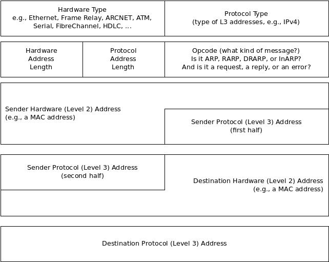
To better understand, let's walk an ARP call. It begins in say, a Web browser, when the browser makes a call to parse the URL. In most cases, that URL contains a hostname (not an IP address), so the following sort of dance takes place:
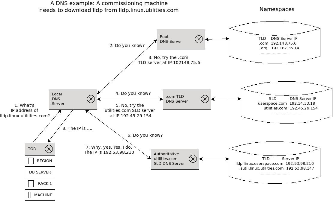
We won't go into this in much detail now, just know that the browser is able to gather an IP address, if it exists. To make the walk-through less confusing, let's assume that we're looking for a host with IP 192.168.17.4.
Next, the browser requests a connection with 192.168.17.4, using the TCP protocol, which sends a connection request, as an IP packet, to 192.168.17.4. Along the way, there is probably more than one router hop.
ARP sends a broadcast request to everything on the relevant subnet. This request looks like the ARP message above, but it's encoded as a MAC frame, which helps to answer the often-fuzzy question, "Is ARP Layer 2 or Layer 3?" As you see, this is an L2 message. Incidentally, ARP only works as a broadcast, by the way; that is, it only works on a broadcast network.
A very important note for some systems like MAAS: ARP requests don't typically span VLANs.
Essentially, this ARP message contains the IP address 192.168.17.4, but no corresponding MAC address in the message. This tells the owner of 192.168.17.4 that it should reply with a similar ARP message, including its MAC address. When the sender receives the ARP reply, it can send the datagram directly to the destination host, embedded in an Ethernet frame, using the MAC address.
By the way, for efficiency, the sending host and the intermediate routers are all doing ARP caching. They copy down the mapping between IP and MAC addresses, holding onto it for about twenty minutes. In terms of most network transactions, twenty minutes is an eternity.
Messages are sent to MAC addresses
We often speak of TCP/IP as if messages are sent from one IP address to another, but that's actually not strictly true. Messages are sent to MAC addresses. IP addresses are only used to get MAC addresses, so the message can go through.
We can return to the air ambulance company to see a practical analogy. A 911 call comes in for "20 Main Street, Yourtown, Yourstate, Yourpostalcode". The address is sent to the pilot of the helicopter, who punches the address into his GPS. The GPS uses the postal address to retrieve the lat/long coordinates, which are then used to guide the helicopter, via satellite navigation.
The same sort of thing happens when you use the GPS navigator in your car. The navigator is translating a logical (postal) address to a physical (lat/long) address on the surface of the earth, calculating a route, and translating that route back to logical landmarks (street names) to let you know how to get there.
By the way, You should also note that ARP only works with IPv4. Certain other protocols, like Point-to-Point Protocol (PPP), don't make use of ARP at all.
ARP sends requests as an Ethernet frame, using the MAC address. If you remember the MAC frame from earlier:
The ARP frame is just a special case of the MAC frame, replacing everything the DSAP, SSAP, control bits, and data with the ARP message shown above. The resulting ARP frame looks something like this:
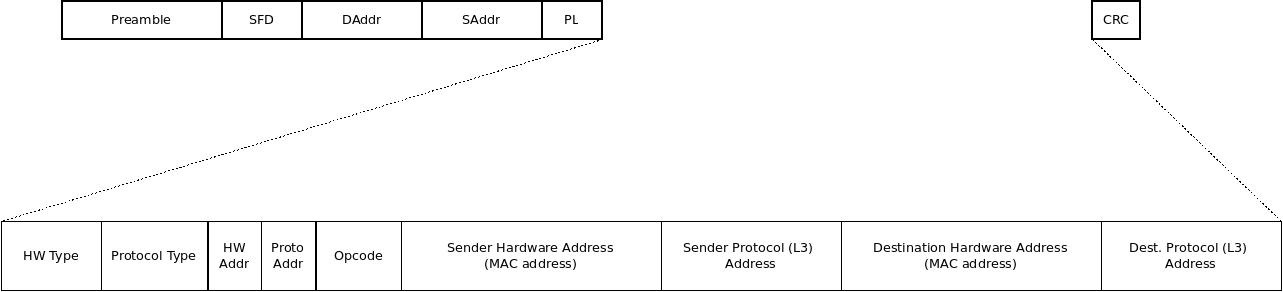
Based on the above diagram, you can see how the ARP request fits into the Ethernet frame to make an ARP frame.
Let's take a look at the ARP cache on a local system, ~cloudburst~. We can do that like this:
stormrider@cloudburst:~$ arp
Address                  HWtype  HWaddress           Flags Mask            Iface
192.168.1.24             ether   0c:8b:7d:f1:51:d3   C                     wlo1
10.250.204.17                    (incomplete)                              mpqemubr0
192.168.1.24             ether   0c:8b:7d:f1:51:d3   C                     enx606d3c645a57
192.168.117.16                   (incomplete)                              virbr0
The columns are mostly obvious, but just in case:
- Address: the IP address that's been cached.
- HWtype: the Hardware Type field, which is blank when there's no MAC address (as is the case in a number of these entries).
- HWaddress: the MAC address of the device. The "incomplete" entries are meant to indicate that an ARP request was sent for that address, but no response was received.
- Flags Mask: this field can have three values: "C" indicates that ARP learned this on its own, based on ARP responses; "M" means that the data was manually entered in the ARP table by a user; and "P" means "Publish," which just tells the host how to respond to incoming ARP packets.
- Iface: the interface name.
In this case, ~virbr0~ and ~mpqemubr0~ are virtual bridges used for different sets of libvirsh VMs that haven't been used for anything in a while. Also note that something called ~lxdbr0~, which is an LXD bridge, doesn't even show up.
Let's see if we can influence that. First, let's take a look using ~ip a~:
stormrider@cloudburst:~$ ip a show up
5: virbr0: <NO-CARRIER,BROADCAST,MULTICAST,UP> mtu 1500 qdisc noqueue state DOWN group default qlen 1000
    link/ether 52:54:00:d6:70:6c brd ff:ff:ff:ff:ff:ff
    inet 192.168.117.1/24 brd 192.168.117.255 scope global virbr0
       valid_lft forever preferred_lft forever
6: mpqemubr0: <NO-CARRIER,BROADCAST,MULTICAST,UP> mtu 1500 qdisc noqueue state DOWN group default qlen 1000
    link/ether 52:54:00:84:0a:4c brd ff:ff:ff:ff:ff:ff
    inet 10.250.204.1/24 brd 10.250.204.255 scope global mpqemubr0
       valid_lft forever preferred_lft forever
7: lxdbr0: <NO-CARRIER,BROADCAST,MULTICAST,UP> mtu 1500 qdisc noqueue state DOWN group default qlen 1000
    link/ether 00:16:3e:e4:2b:fe brd ff:ff:ff:ff:ff:ff
    inet 10.90.195.1/24 scope global lxdbr0
       valid_lft forever preferred_lft forever
    inet6 fd42:1fc6:f588:d0b8::1/64 scope global
       valid_lft forever preferred_lft forever
You'll see that all three bridges are in a DOWN state, and again, ~lxdbr0~ is so cold that it doesn't even show up in the ARP table. Let's bring up a LXD VM connected to ~lxdbr0~ and look at the ARP table again:
stormrider@cloudburst:~$ arp
Address                  HWtype  HWaddress           Flags Mask            Iface
192.168.1.24             ether   0c:8b:7d:f1:51:d3   C                     wlo1
10.250.204.17                    (incomplete)                              mpqemubr0
192.168.1.24             ether   0c:8b:7d:f1:51:d3   C                     enx606d3c645a57
192.168.117.16                   (incomplete)                              virbr0
10.90.195.16             ether   00:16:3e:fc:71:98   C                     lxdbr0
Note that the ~lxdbr0~ bridge now shows up and has a MAC address, too -- no incomplete entry here. If we look at the MAC address of ~lxdbr0~ in the ~ip~ listing, we'll see it matches up.
Those "(incomplete)" entries are old. They've been cached, but no traffic has passed through those bridges in a really long time. The cache is just persistent in holding onto the IP addresses, but not the MAC addresses (since they could be stale). We can prove this to ourselves by clearing the cache:
stormrider@cloudburst:~$ sudo ip -s neigh flush all
[sudo] password for stormrider:

*Round 1, deleting 18 entries ***
*Flush is complete after 1 round ***
...and rebuilding the ARP table:
stormrider@cloudburst:~$ arp
Address                  HWtype  HWaddress           Flags Mask            Iface
192.168.1.24             ether   0c:8b:7d:f1:51:d3   C                     wlo1
192.168.1.24             ether   0c:8b:7d:f1:51:d3   C                     enx606d3c645a57
10.90.195.16             ether   00:16:3e:fc:71:98   C                     lxdbr0
Another form of ARP is promiscuous ARP, in which some proxy host pretends to be the destination host and provides an ARP response on behalf of the actual destination host. You shouldn't use this form of ARP unless there's no other choice. You can Google it (and use it at your own risk), but it won't be described here.
There is also gratuitous ARP, when the source and destination IP addresses are the same. This can be used for at least two purposes:
-
To find out if someone else already has the source machine's IPv4 address, a technique called Address Conflict Detection by some references.
-
To update the source machine's new MAC address (e.g., a new NIC card was installed) in upstream ARP cache entries. This is something akin to pre-caching MAC addresses before they're actually needed.
You can read more about^ these (and many more) nuances of ARP, but this introduction should answer most of the immediate questions.
If the Internet Protocol (IP) is connectionless, the transport layer is all about connections. The transport-layer protocol in use -- we'll talk exclusively about Transmission Control Protocol or TCP here -- the L4 protocol is the last place in the stack where the entire message exists in one piece. L4 breaks up larger messages into segments. Each segment gets a TCP header, and gets passed on to L3 where it becomes an IP packet.
Here's a diagram of the L4-to-L3 hand-off:
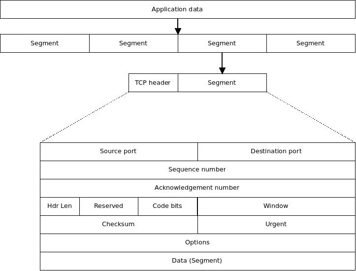
We can get a pretty good idea what happens at Layer 4 just by decoding the contents of the TCP header. It contains the following fields:
-
Source port: the application port number of the host sending the data. For example, if this is an FTP message, the source port would probably be 21.
-
Destination port: the port number of the application requested on the destination host. If this is FTP, again this port would likely be 21.
-
Sequence number: the sequence number of this segment of data, to help the other end put the data back together in the correct order, as well as help Level 4 on the receiving end know whether a packet's been dropped or lost.
-
Acknowledgement number: essentially, the next sequence number the destination host is expecting; used to "gate" packets through the connection.
-
TCP header length: given to know where the data begins.
-
Reserved: reserved for future use, basically; currently always set to 0.
-
Code bits: essentially a set of flags; see the list below.
-
Window: used to negotiate the "window" size, that is, how many bytes the destination host is willing to receive at once; this allows for the most efficient transmission possible, based on the characteristics of the two communicating hosts.
-
Checksum (CRC): used to check the integrity of the segment.
-
Urgent pointer: data byte count where urgent data ends; used if the urgent flag is set (see below).
The code bits can indicate the following things:
-
URG: indicates that the urgent pointer field is meaningful, used to prioritise this message over other messages.
-
ACK: used to acknowledge successful delivery of the previous segment.
-
PSH: push notification; tells the receiving host the message is complete, you can push the data to the application.
-
RST: request a connection reset when the error level reaches a certain threshold; basically, "let's try that again from the top." This is considered an abnormal termination of the TCP connection.
-
SYN: used for a three-way TCP handshake; this handshake is how sender and receiver sync up; it serves a purpose similar to the preamble in a MAC frame, but at a different level of synchronisation.
-
FIN: we're done, close the connection. This is considered a normal termination of a TCP connection.
-
NS/CWR/ECE: used to provide Explicit Congestion Notification; note that OSI provides several methods for endpoints to know that the network is congested.
As you can see from the bytes above, TCP is all about the state of a connection, which is basically the same as a phone call. When you pick up the receiver, you and the caller exchange information. You say "bye" when the call is over. If it's a bad connection or one end suddenly gets noisy (think jack-hammers outside), one of you can reset the connection by saying, "Let me call you back in a minute." Take a minute and try to see how the other header bytes fit this analogy.
Also like a telephone call, TCP provides a connection (the call, however long it lasts), flow control (provided by the two parties on the call), multiplexing (handled by the two handsets, basically letting through multiple frequencies and sounds, so that you can get the tone and breath sounds of the other person, not just their raw words). Likewise, the two parties try to handle the reliability of the connection by making sure you understand each other.
The analogy spreads a little because some of the items (connection, multiplexing) are handled by the telephone, and some are handled by the people operating the telephone (flow control, reliability). In the network, the Level 4 protocol stack handles it all.
There is a lot more to know about TCP, but most of it isn't directly relevant for MAAS networking. Instead, we direct you to the excellent Wikipedia article about TCP^. Going forward, we'll only bring up specific transport layer elements as we need them.
Because IP addresses are hard for humans to remember, the Internet supports the use of host names to identify hosts. These host names are associated with the host's actual IP address in a server known as a Domain Name server. The overall protocol is known as the Domain Name System^.
This section summarises a number of other networking elements that may occasionally come up when working with MAAS networks. These include:
- Client
- Hub
- LAN
- MAC address
- MAN
- Network cable
- Patch panel
- Repeater
- Router
- Server
- Switch
- Network topology
- WAN
In the client/server age, the lines between client and server are blurred and sometimes reversible. For the purposes of MAAS and general networking principles, we can define a client^ as a node that uses shared resources via a network. If that same client provides shared resources to other nodes, it could also be considered a server.
A server^ is a node that provides shared resources to clients via a network. If that same server uses shared resources from other nodes, it could also be considered a client, but only in that context.
Hubs^ essentially started as repeaters. While they may be able to connect more than two computers together (i.e., multiple RJ45 ports)^, they provide no improvement over simple bus networks, since every connected NIC must examine every packet. They are rarely used any more.
A MAC address^ or "media access control" address is a unique address or "physical address" associated with a network interface. They are 48 bits in length, which allows for 280 trillion devices, arranged into six hexadecimal octets, separated by colons or dashes. Every computer in the world theoretically has a unique MAC address. You can identify a node's IP address with the command ipconfig /all.
Network cables^ are special cables that connect non-wireless-based nodes. They consist of our pairs of insulated, 24-gauge wire, colour-coded (solid/striped)^, usually in four colours: blue, green, orange, and brown. The matching colour pairs are twisted together, each pair at a different turn rate to prevent electromagnetic interference between pairs. These twists must be maintained all the way up to the (RJ45) connector.
Even with insulation, careful twisting, and connector-termination, natural losses in the cable cause the network signals to become too weak to maintain reliable data rates after a certain length. In the case of Cat 5e cable, the maximum cable length is 100 meters to maintain 1Gb per second. For Cat 6, the max length to maintain 10Gb per second is 55 meters. These limits are overcome with repeaters, which amplify the signal and relay it to the next repeater or NIC.
Technically, a repeater^ is a network signal amplifier with two RJ45 connectors which adds one maximum length (for the cable type) to the network connection or "run." In practice, repeaters usually come in the form of hubs or switches^, which can usually perform other functions as well.
A switch^ is a "smart" device that connects cables from nodes to make networks. Like a hub, a switch amplifies signals, that is, it acts as a repeater. Switches learn by induction which cables receive which IP addresses. Over time a switch will direct each packet only to devices which indicate that they will accept the addresses associated with those packets.
Topology^ describes how nodes are connected to a network, specifically referring to the shapes made by the cables and the paths that packets can take. There are probably as many topologies are there are shapes, but here are some of the most common:
-
Bus topology: the most basic network topology, a group of computers connected to a single, long cable. In this configuration, every computer sees every packet. A hub network, for instance, is still a bus topology, because every machine sees every packet.
-
Star or switch topology: a group of computers connected to a switch. As the switch learns where packets are supposed to go, the star quickly evolves so that only packets are only seen by computers that are intended to receive the packet.
-
Backbone topology: a hybrid network configuration in which several stars are connected to a bus.
-
Daisy-chain topology: stars connected to stars, or more accurately, switches connected to switches.
-
Mesh topology: nodes with multiple interfaces and multiple connections. Useful where wide-area networks (WAN) where there would otherwise be lots of intermediaries. Not popular or particularly cost effective for LAN networks.
A patch panel^ is simply a 24- to 48-port panel of connectors that can link together three- to ten-foot cables. A patch panel allows jumpers from network runs to devices in racks, without putting strain and "cable creep" on long runs.
Besides topology, networks can also be classified by their size, range, or "reach." One such classification is the Local Area Network (LAN)^, which connects computers in close proximity (about 300 feet)^.
A WAN (wide area network)^ is a network which connects LANs across large geographic distances, e.g., thousands of miles.
A metro area network or MAN^ connects LANs over a smaller area, like a city or urban footprint. Basically, if it isn't really a WAN, but you can't connect it with cables, it's usually considered a MAN.
A router^ is a device that transfers packets from one network to another. Unlike switches, which only ensure that pre-addressed packets get to the correct recipient machines, routers actually modify or encapsulate packets to ensure that they can travel on other networks to reach a remote destination. Choices about routing are so important that we'll spend a great deal of time on the subject^ when we learn about cloud networking.